

Blog
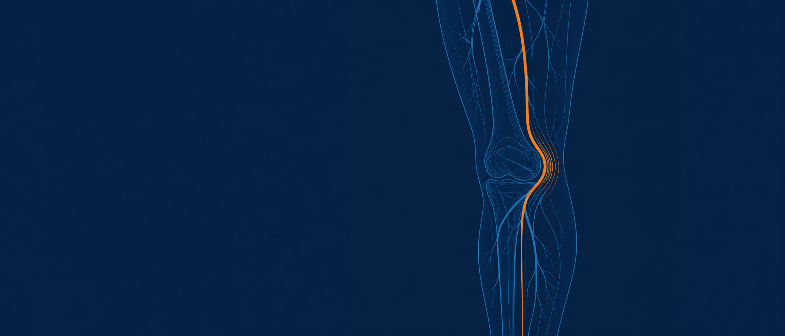
The superficial femoral artery is one of the most mechanically hostile places you can put a permanent implant. With every stride, it compresses along its axis, bends, twists, and shortens. Cross the knee into the popliteal segment and the loading gets worse. A stent that survives a bench radial test can still fracture in vivo within a year if it was designed as though the vessel holds still. This is the defining truth of peripheral vascular work: the anatomy does not hold still, and it does not forgive a device that ignores what it does.
It also means “peripheral” is not a single design target. The iliac, the SFA, the popliteal, and the below-the-knee tibial vessels are four different mechanical problems wearing the same label. That range constrains both halves of any peripheral program at once: the implant you leave behind and the delivery system you use to place it. As we argued in The implant alone isn’t enough and the accompanying video series, those two devices cannot be designed apart. This article is the engineering half of that argument. Here is what co-development actually looks like when the anatomy sets the terms.
The peripheral vessel is a moving target.
Start with the anatomy, because it dictates everything downstream.
The iliac arteries are relatively large, commonly in the 6 to 10 mm range, and the challenge there is often tortuosity and heavy calcification rather than cyclic motion. Crossing a calcified, angulated iliac lesion is a trackability and radial-force problem. Fatigue is secondary.
The SFA is the opposite. Diameters run roughly 4 to 6 mm, but the segment sits in the thigh and deforms with every hip and knee flexion. Published biomechanical work has documented meaningful axial compression, bending, and torsion in the SFA and popliteal segments during limb movement, with the artery shortening along its axis as the knee bends.
Between pulsatile flow and the mechanical loading of ordinary limb movement, an SFA stent accumulates millions of load cycles a year. It is not a static scaffold. It is a fatigue-loaded structure, and fracture is a real and documented failure mode for peripheral stents that were not designed for it.
Below the knee, the tibial and peroneal arteries drop to roughly 2 to 4 mm, lesions are long and diffuse, and the margin for profile and flexibility shrinks accordingly. Calcification runs through all of these beds and changes the problem again. Calcium resists expansion, degrades wall apposition, and raises crossing force, which pushes back on both the implant’s radial design and the delivery system’s pushability.
The point of walking through the bed this way is that no single implant architecture or delivery configuration serves all of it. A design optimized for a calcified iliac lesion is the wrong design for a flexing SFA. Both halves of the system inherit that constraint set. Neither can be finalized without knowing which segment it is built for.
Designing the implant for peripheral anatomy.
Most peripheral stents are self-expanding nitinol, and nitinol is where the first tradeoffs live. Its superelasticity lets a stent be crimped into a small delivery profile and recover its shape on release, but the two forces that matter, chronic outward force (COF) and radial resistive force (RRF), pull design decisions in competing directions. Higher radial support helps hold a calcified or recoiling vessel open. It also tends to cost you flexibility and crossing profile, and it raises the force the delivery system has to manage on deployment.
Frame geometry mediates that tradeoff. Open-cell laser-cut designs flex and conform better through tortuous or mobile anatomy. Closed-cell designs give more uniform scaffolding and lesion coverage at the expense of conformability. For the SFA specifically, fatigue resistance moves to the front of the list, which drives strut geometry, connector design, and the decision between a laser-cut tube and a woven or braided construction that distributes strain differently under bending.
A quick orientation to the levers and what each one costs:
| Implant design lever | Improves | Trades against |
|---|---|---|
| Higher radial force (COF/RRF) | Vessel support, resistance to recoil and calcium | Flexibility, crossing profile, deployment force |
| Open-cell frame geometry | Conformability, flexibility in tortuous/mobile beds | Scaffolding uniformity, lesion coverage |
| Closed-cell frame geometry | Uniform coverage, plaque containment | Conformability, deliverability through tortuosity |
| Added covering (stent graft) | Flow isolation, exclusion, patency in specific indications | Crossing profile, flexibility, deployment force |
| Lower crimped profile | Deliverability, smaller access, distal reach | Achievable radial force, wall thickness options |
The covering row is where a large share of peripheral implant value sits, and it is where the manufacturing gets genuinely hard. Covered stents and stent grafts used in peripheral aneurysm exclusion, in-stent restenosis, and AV access rely on a covering that has to stay bonded to a moving frame for the life of the device. Expanded PTFE (ePTFE) is a common choice because its node-and-fibril microstructure can be tuned for porosity and compliance, and its behavior under repeated flexion is well characterized.
The engineering problem is the marriage of covering to frame. Encapsulating a nitinol frame between ePTFE layers, or laminating a covering to one face of it, has to hold bond integrity through crimping, deployment, and years of cyclic loading without delamination, wrinkling that disturbs flow, or the kind of stiffening that defeats the whole point of a flexible peripheral frame. Every covering adds crossing profile and reduces flexibility. That is the unavoidable cost, and managing it is a large part of what separates a manufacturable covered peripheral device from a bench concept. This encapsulation and lamination work is a core Aptyx Interventional Systems capability, and it is where implant-side manufacturing depth shows up.
One implant property matters so much to the other half of the system that it deserves naming here: crimped profile. The diameter you can crimp the finished implant down to, covering and all, is the number the delivery system inherits. It sets the sheath, the access, and much of the deployment behavior. That handoff is the subject of section five.
Two boundaries worth stating plainly. The nitinol frame itself is typically laser-cut and electropolished, processes we treat here at the design level rather than claiming as in-house Aptyx operations. And ePTFE is a distinct material and process from the PTFE and FEP heat-shrink and liner work that sits outside our scope. The implant-side strength being described is the covering, encapsulation, and lamination, not frame fabrication or fluoropolymer extrusion.
Designing the delivery system for peripheral anatomy.
If the implant is built for the destination, the delivery system is built for the journey, and peripheral journeys are long. Femoral or radial access to an SFA or below-the-knee target can mean working lengths well past 100 cm, over which the operator has to transmit push and torque at the handle into precise motion at the tip while the shaft negotiates the same tortuosity and calcium the implant will eventually sit in.
That sets up the central shaft tradeoff: pushability versus trackability. A stiff shaft transmits force well but fights its way through curves and can prolapse or straighten the anatomy. A flexible shaft tracks beautifully and transmits force poorly. The resolution is not one durometer but a gradient, and a durometer gradient is only the entry point. A common construction steps from a stiffer proximal segment to a soft distal tip, using a family such as Pebax (PEBA) across a range of roughly Shore 35D to 72D, with transitions placed to match where the catheter needs column strength versus where it needs to bend. [SME REVIEW]: confirm the durometer family and transition scheme you want represented.
Real performance often demands more than a single-material gradient. Where push efficiency and torque transmission are critical, the inner shaft may be a jacketed, laser-cut hypotube rather than polymer alone, tuned by cut pattern to stay stiff proximally and flexible distally. Advanced shafts also layer materials and additives, and use co-extrusions or tri-layer extrusions to combine a lubricious inner surface, a tie or reinforcement layer, and a tuned outer jacket in a single wall. Multilayer and co-extruded shaft construction is core extrusion work, and it is where a lot of delivery-system performance is won or lost. (The hypotube itself is a machined metal component we treat here at the design level, consistent with the frame-fabrication boundary above.)
Reinforcement carries the torque and the kink resistance. Braided or coiled layers embedded in the shaft wall let the operator turn the handle and have the tip respond, and they keep the shaft from kinking at a tight bend and blocking the lumen. Reflow bonding fuses these segments and layers into a continuous shaft with controlled transitions rather than abrupt stiffness steps that create kink points. Balancing reinforcement density, liner selection, and durometer against each other across the full working length is most of the delivery shaft design problem.
Deployment mechanics are the third piece. Most self-expanding peripheral stents are held crimped inside an outer sheath and released by retracting that sheath while a stable inner member holds the implant in place. The force required to retract the sheath, and its smoothness, determine how controlled the deployment feels and how accurately the operator can land the device. High deployment force, or force that releases unevenly, translates directly into placement error. Smooth, accurate release also depends on the friction relationship at the implant interface: when stent-to-inner-member friction stays higher than stent-to-sheath friction, the implant holds its position on the inner member as the sheath withdraws and comes free without foreshortening or jumping in the system. Repositionable and recapturable designs raise the bar further, because the system now has to reconstrain a partially deployed implant without damaging it or the vessel.
Placement accuracy also depends on what the operator can see. Peripheral deployment is image-guided, so radiopaque markers have to sit where they communicate the real deployment landmarks, typically the working ends of the implant and key reference points on the delivery system. Marker bands in radiopaque metals such as platinum-iridium or gold mark discrete locations, while radiopaque fillers such as tungsten compounded into the polymer, for example in a molded tip, make features visible without a separate band. Marker placement and swaging, tipping, and forming are established Aptyx secondary-process operations.
Where the two meet: co-optimizing the implant and delivery interface.
The reason co-development matters is not organizational tidiness. It is that a specific set of decisions cannot be made on either side alone. They live at the interface, and getting them wrong on one side shows up as failure on the other.
Crimped profile against sheath ID. The implant’s crimped outer diameter has to fit inside the sheath’s inner diameter with enough clearance to deploy smoothly, but not so much that the implant floats and loses positional control. Push the implant’s radial force or add a covering and the crimped profile grows, which forces a larger sheath, which raises the access profile and reduces distal reach in small vessels. This is a coupled equation. It cannot be solved by the implant team and the delivery team in separate rooms.
Radial force against deployment and recapture force. The same chronic outward force that makes an implant hold a calcified vessel open is the force the sheath has to restrain and then release. Higher COF means higher deployment force and, for recapturable designs, higher resheathing force. Get the friction balance wrong and the implant can behave like a watermelon seed, shooting out of the system ahead of the intended release. The safeguard is a deliberate friction relationship: stent-to-inner-member friction has to exceed stent-to-outer-sheath friction, so the implant stays seated on the inner member as the sheath withdraws. An implant optimized purely for radial support, without that friction balance designed in, can produce a delivery system that deploys with a lurch. Tuning radial force and friction together is the only way to get both vessel support and controlled placement.
Length shift on deployment. Here the construction type matters, and so does friction. Laser-cut tube stents largely hold their length through deployment when the friction balance is correct, so they land where the operator places them. Braided and woven constructions are different: they foreshorten geometrically as they expand toward vessel diameter, and that length change is inherent to how the braid opens, not just a system artifact. Two things are worth separating. Foreshortening in the system, during sheath withdrawal, is largely governed by the same friction relationship above and can be controlled by design. Foreshortening in the vessel, as a braided implant expands to its deployed diameter, is a property of the implant that the delivery sequence and the operator have to account for. When neither is managed, the device lands long or short. This is exactly the problem behind the braided-stent case referenced in our co-development article. A braided stent requiring proximal-to-distal deployment was paired with a custom suture-release delivery mechanism so that the release sequence and the implant’s length-shift dynamics were solved as one design rather than discovered in the clinic. Co-developing the release mechanism with the implant’s expansion behavior took length shift from a deployment hazard to a controlled, predictable step.
The interface reduces to a short list of coupled parameters, each owned by neither side alone:
| Coupled parameter | Implant side | Delivery side | What goes wrong if decoupled |
|---|---|---|---|
| Crimped profile vs. sheath ID | Radial force, covering, wall thickness set crimped OD | Sheath ID, access profile, distal reach | Oversized sheath, lost reach, or an implant that floats and mistracks |
| Radial force vs. deployment force | Chronic outward force for vessel support | Sheath retraction and resheathing force | Device that deploys with a lurch, poor landing accuracy |
| Length shift vs. release sequence | Foreshortening on expansion, worst in braided frames | Deployment sequence and operator reference points | Device lands long or short; recapture harder than expected |
The pattern across all three is the same. Each is a property the implant exports and the delivery system imports, or the reverse. Designed in sequence, they become late-stage surprises that force redesign of whichever device is easier to change, which is rarely the right one. Designed together, they become tuned parameters. That is the manufacturability case for the systems approach, stated in the concrete terms an engineer can act on.
What to ask a manufacturing partner.
If you are scoping a peripheral implant and delivery program, these questions separate a partner who has built coupled systems from one who has built components. Design for manufacturability (DFM) is the ability to design a device so it can be built repeatably at quality, and every question below is a DFM question.
- Can you show experience co-developing an implant and its delivery system for the same program, not just one or the other?
- For covered devices, how do you validate covering-to-frame bond integrity through crimping, deployment, and cyclic loading, and what does delamination testing look like?
- How do you manage the crimped-profile-to-sheath-ID relationship as a coupled parameter, and at what point in development do you lock it?
- What is your approach to durometer transitions and reinforcement across long peripheral working lengths, and how do you validate trackability and kink resistance?
- How do you measure and control deployment and recapture force, and how do you tie those back to the implant’s radial design?
- How do you handle length shift and marker placement so deployment accuracy is designed in rather than trained around?
- What process capability (Cpk, the index describing how reliably a process holds a spec, with 1.33 a common minimum target) do you sustain on the critical dimensions, and how do you demonstrate it across production lots?
- How do your quality system, cleanroom classification (ISO Class 7 or 8), and validation sequence (IQ/OQ/PQ) support the device class you are building toward?
The takeaway.
Peripheral vascular programs succeed or stall on how well the implant and its delivery system are designed against the same anatomy and against each other.
- The peripheral bed is not one target. Iliac, SFA, popliteal, and below-the-knee anatomy each set different constraints on radial force, profile, flexibility, and fatigue resistance.
- The implant’s hardest manufacturing problems, especially covering, encapsulation, and lamination for stent grafts, determine its crimped profile and much of its deliverability.
- The delivery system’s job, in addition to implant protection, is force transmission and controlled, visible deployment over long, tortuous access.
- The decisions that matter most, crimped profile against sheath ID, radial force against deployment force, and length shift, live at the interface and cannot be made on either side alone.
If you are building a peripheral vascular implant and delivery program and want to pressure-test the design for manufacturability before it hardens, start the conversation with Aptyx Interventional Systems engineering.